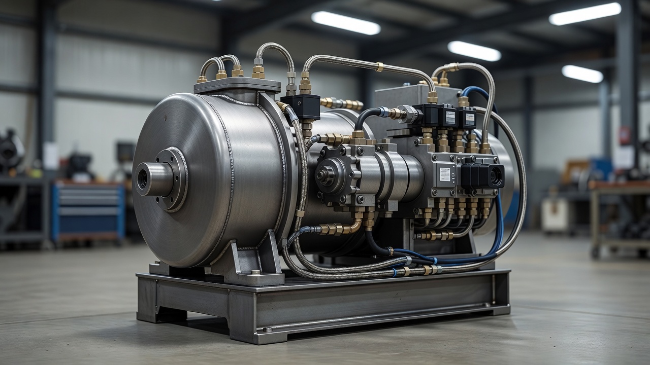
Unlike traction elevators that utilize overhead mechanical hoisting, hydraulic elevators operate on the principles of fluid dynamics. An electric pump forces pressurized fluid—traditionally petroleum-based oil, but increasingly biodegradable alternatives—into a cylinder. This pressure pushes a piston upward, elevating the cab. To descend, a valve opens, allowing the fluid to flow back into the reservoir under the sheer weight of the car, utilizing gravity rather than electric power.
Types of Hydraulic Layouts
Hydraulic elevators are categorized primarily by where the lifting cylinder is located in relation to the cab. The structural capabilities of the building heavily dictate this choice.
Holed (Conventional) Hydraulics
In a holed hydraulic system, a deep cylindrical hole is bored into the earth directly below the elevator pit. The hydraulic cylinder extends into this hole. The depth of the hole must precisely match the maximum vertical travel distance of the elevator. Because the piston supports the cab from directly underneath, this setup is incredibly stable and capable of lifting tremendous loads, making it the standard for heavy industrial freight elevators. However, drilling the jack hole can be expensive and is occasionally prohibited due to unstable soil, bedrock, or proximity to the water table.
Holeless Hydraulics
To circumvent the need for deep drilling, holeless hydraulic systems employ cylinders mounted above ground within the hoistway, alongside the elevator cab. These are available in two primary configurations:
- Direct Acting: Pistons mounted on one or both sides of the cab push it upward directly. These are limited in travel height because a very long un-braced piston would be susceptible to buckling under load.
- Roped Hydraulic: To extend the travel height of holeless systems, a rope and sheave mechanism is attached to the top of the piston. For every meter the piston moves, the roping ratio (usually 1:2) moves the elevator cab two meters. This allows hydraulic systems to serve up to six floors without underground drilling.
Energy and Environmental Implications
Hydraulic elevators present unique trade-offs regarding energy consumption and environmental impact. While descending requires virtually zero electricity (as gravity forces the fluid back through a controlled valve), ascending requires the pump to move the entire weight of the cab and passengers—unlike traction systems which use counterweights.
Consequently, hydraulic pumps draw significant electrical current during the up-travel phase. Over high-frequency usage, this results in greater total energy consumption compared to a traction equivalent.
Environmentally, the risk of underground cylinders corroding and leaking hydraulic fluid into the soil was historically a concern for holed systems. Today, this risk is mitigated through PVC jack liners, moisture sensors, and the widespread adoption of vegetable-based, biodegradable hydraulic fluids that pose no threat to groundwater.
Pros and Cons
| Advantages | Disadvantages |
|---|---|
| Lower initial installation cost and complexity. | Higher energy consumption during upward travel. |
| Extremely high weight capacity (ideal for freight). | Limited travel height (typically up to 18 meters / 60 feet). |
| No overhead machine room required; structural loads are on the pit floor. | Slower travel speeds (usually capped around 0.75 m/s). |
| Smoother ride quality at low speeds compared to geared traction. | Hydraulic oil temperature variations can affect ride leveling accuracy. |
Maintenance Profile
Hydraulic elevators generally contain fewer moving parts than traction systems. The primary maintenance focus is the pump unit—checking fluid levels, ensuring valves are clean and properly adjusted, and monitoring for leaks around the piston packings (seals). If the elevator fails to stop perfectly level with the floor, it typically indicates that the control valve needs recalibration or that the fluid temperature is fluctuating significantly due to heavy use or environmental factors. Oil coolers or tank heaters are often installed to maintain a consistent fluid viscosity.